Showing posts with label JWST. Show all posts

Wednesday, April 28, 2010

Webb Telescope Passes Mission Design Review Milestone


NASA's Northrop Grumman-built James Webb Space Telescope has passed its most significant mission milestone to date, the Mission Critical Design Review, or MCDR. This signifies the integrated observatory will meet all science and engineering requirements for its mission.

"I'm delighted by this news and proud of the Webb program's great technical achievements," said Eric Smith, Webb telescope program scientist at NASA Headquarters in Washington.

"The independent team conducting the review confirmed the designs, hardware and test plans for Webb will deliver the fantastic capabilities always envisioned for NASA's next major space observatory. The scientific successor to Hubble is making great progress."

NASA's Goddard Space Flight Center, in Greenbelt, Md., manages the mission. Northrop Grumman, Redondo Beach, Calif., is leading the design and development effort.

"This program landmark is the capstone of seven years of intense, focused effort on the part of NASA, Northrop Grumman and our program team members," said David DiCarlo, sector vice president and general manager of Northrop Grumman Space Systems.

"We have always had high confidence that our observatory design would meet the goals of this pioneering science mission. This achievement testifies to that, as well as to our close working partnership with NASA."

The MCDR encompassed all previous design reviews including the Integrated Science Instrument Module review in March 2009; the Optical Telescope Element review completed in October 2009; and the Sunshield review completed in January 2010. The project schedule will undergo a review during the next few months.

The spacecraft design, which passed a preliminary review in 2009, will continue toward final approval next year.

The review also brought together multiple modeling and analysis tools. Because the observatory is too large for validation by actual testing, complex models of how it will behave during launch and in space environments are being integrated. The models are compared with prior test and review results from the observatory's components.

Although the MCDR approved the telescope design and gave the official go-ahead for manufacturing, hardware development on the mirror segments has been in progress for several years.

Eighteen primary mirror segments are in the process of cryo-polishing and testing at Ball Aerospace in Huntsville, Ala. Manufacturing on the backplane, the structure that supports the mirror segments, is well underway at Alliant Techsystems, or ATK, in Magna, Utah.

This month ITT Corp. in Rochester, N.Y., demonstrated robotic mirror installation equipment designed to position segments on the backplane. The segments' position will be fine-tuned to tolerances of a fraction of the width of a human hair. The telescope's sunshield moved into its fabrication and testing phase earlier this year.

The three major elements of Webb - the Integrated Science Instrument Module, Optical Telescope Element and the spacecraft itself - will proceed through hardware production, assembly and testing prior to delivery for observatory integration and testing scheduled to begin in 2012.

The Webb is the premier next-generation space observatory for exploring deep space phenomena from distant galaxies to nearby planets and stars.

The telescope will provide clues about the formation of the universe and the evolution of our own solar system, from the first light after the Big Bang to the formation of star systems capable of supporting life on planets like Earth. The telescope is a joint project of NASA, the European Space Agency and the Canadian Space Agency.

Wednesday, March 31, 2010

A View of the JWST NIRSpec Instrument


The Universe has always set the standard for colors. It produces all possible combinations of colors, granted not always in the visible light spectrum. But figuring out how these nuances intertwine is absolutely essential to, for example, determining the distance a certain object is from Earth, what chemicals it contains and so on. This is why the most impressive space observatory ever built, the James Webb Space Telescope (JWST), will feature an instrument perfectly capable of extracting this sort of data from whatever wavelengths of light enter its detectors.

The Near-Infrared Spectrograph (NIRSpec) device will be one of the most advanced spectrographs ever developed, and undoubtedly the most complex to ever fly to space. EADS/Astrium is the European Space Agency's (ESA) prime contractor for the overall NIRSpec instrument, but some of the components were constructed at the NASA Goddard Space Flight Center (GSFC), in Greenbelt, Maryland. The prototype for the actual NIRSpec instrument that will fly on the JWST recently arrived at the GSFC for preliminary testing, from its construction site in Germany.

“A spectrograph is an instrument that separates light into a spectrum. One example of a spectrograph that most folks know about is a chandelier (or diamond ring). When sunlight shines through it, it breaks it up into colors. NIRSpec analyzes those colors from deep space to help us solve mysteries,” explains GSFC expert Bernie Rauscher. He is the deputy project scientist of the telescope's Integrated Science Instrument Module (ISIM) and also the principal investigator of the NIRSpec Detector Subsystem.

This particular spectrograph will have the ability to analyze more than 100 cosmic objects at the same time, as its components were especially designed for this task. The instrument will collect readings in the infrared portion of the electromagnetic spectrum, which will enable researchers analyzing data from the instrument to determine the age, chemical composition and distances of faint galaxies. One of the primary mission goals for the James Webb Space Telescope will be to determine how galaxies began to form in the early Universe, and so this ability that the NIRSpec has will be absolutely fundamental to completing its mission.

Saturday, March 20, 2010

JWST MIRI Replica Arrives at NASA Goddard


Image comment: The MIRI Structural Thermal Model at the Science and Technology Facilities Council’s Rutherford Appleton Laboratory
Image credits: Science and Technology Facilities Council (STFC)

As the Hubble Space Telescope begins to approach its limits, the American space agency is currently working on creating a replacement. Called the James Webb Space Telescope (JWT), the new observatory will be the largest one ever delivered to orbit. However, designing it is very difficult, as some of the technologies that are needed to make it a reality have yet to be developed. But progress is taking place nonetheless, with the spacecraft's heat shields already clearing tests, and some of its mirrors completed. Now, the time has come to test one of its primary scientific instruments.

The Mid InfraRed Instrument (MIRI) is one of the most important components of the new telescope. As such, it needs to undergo extensive testing, so that engineers can ensure it's both highly sensitive, and resistant to the rigors of flying in outer space and surviving a rocket launch. As part of these efforts, a working replica of the MIRI has been recently delivered to the NASA Goddard Space Flight Center, in Greenbelt, Maryland. Experts here call the instrument “the pioneering camera and spectrometer for the James Webb Space Telescope,” Space Fellowship reports.

The replica came a long way to reach Goddard. It was recently shipped from the United Kingdom, where it was produced at the Rutherford Appleton Laboratory, a laboratory operated by the Science and Technology Facilities Council (STFC/RAL). The new observatory represents the fruit of an international collaboration that includes NASA, the European Space Agency (ESA) and the Canadian Space Agency (CSA). These organizations agreed that the best possible successor to Hubble was a telescope that would be larger, and also capable of observing the Universe in infrared wavelengths.

“Receipt of the MIRI structural thermal model (STM) represents a major milestone in eight years of development work by the joint European Space Agency (ESA) and NASA Jet Propulsion Laboratory (JPL) instrument team. Tests with this prototype model of the MIRI, conducted at Rutherford Appleton Laboratories in the UK, have shown that this science instrument is on track to meet all of its performance requirements. Upon receipt of the STM, Goddard engineers will begin testing it with supporting systems in the Webb telescope Integrated Science Instrument Module to facilitate smooth integration of the flight model,” JWST Science Instrument Payload project scientist Matt Greenhouse, who is based at Goddard, says.

Saturday, February 13, 2010

JWST Sunshield Passes Critical Design Review


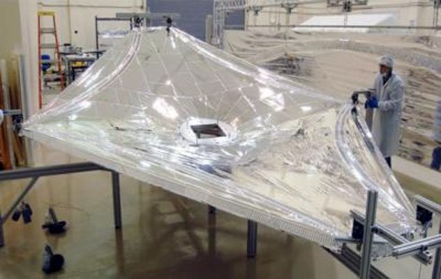
Image comment: This is a photo of the 1/3 scale sunshield membranes undergoing final inspection at the Nexolve facility in Hunstville, Alabama. The full-scale sunshield will fly on the JWST in 2014
Image credits: Nexvolve

The James Webb Space Telescope (JWST) will be the largest observation instrument ever delivered into space during a single rocket launch. Only the International Space Station (ISS) will exceed it in size, but it will come nowhere near its capabilities of observing the early Universe in infrared wavelengths. But, in addition to the difficulties associated with deploying such a behemoth into orbit, engineers also need to figure out a way of protecting its highly sensitive instruments from stray radiation coming from the Sun, the Earth or the Moon. And this is where the shield steps in.

The sunshield the JWST will employ is about the size of a tennis court, and is made up of five overlapping layers of material. Its mission is fairly straightforward, namely to prevent any photons from entering the telescope's mirrors. Just recently, the shield passed a design review test, the most important it had to face. The investigation determined that the design stage was complete, and that the structure met mission requirements. It is being developed by Northrop Grumman, a corporation that has been contracted by the NASA Goddard Space Flight Center, in Greenbelt, Maryland.

The tests took place between January 11-14, in Redondo Beach, California. “Passing this review is the culmination of years of intense effort meeting the unique challenges that have defined this mission. This is the first time a sunshield of this size and complexity will fly on a space telescope. We've achieved a very significant mission-critical milestone with this important validation of our sunshield design,” Northrop Grumman Aerospace Systems JWST telescope Program Manager Scott Willoughby says. The current design achieved thermal, deployment and stray-light targets, and is therefore ready to enter the manufacturing stage.

“There are no text books or guidelines on how to design and build a deployable sunshield of this size. Nearly a decade ago NASA and Northrop Grumman had to start from scratch and literally invent the techniques, materials, and mechanisms needed to do the job. We still have quite the challenge in front of us now that we start into the fabrication and testing phase but it's also a very exciting time,” GSFC JWST telescope sunshield Manager Keith Parrish shares. He adds that the tests consisted of 18 separate sub-assembly design audits, which were aimed at analyzing the performance of individual systems. Another thorough study was conducted on the points where these systems interlaced.

The Webb telescope is NASA's next-generation premier space observatory, exploring deep space phenomena from distant galaxies to nearby planets and stars. The Webb telescope will give scientists clues about the formation of the Universe and the evolution of our own solar system, from the first light after the Big Bang to the formation of star systems capable of supporting life on planets like the Earth. Expected to launch in 2014, the telescope is a joint project of NASA, the European Space Agency (ESA) and the Canadian Space Agency (CSA).

Tuesday, July 7, 2009

James Webb Space Telescope Core Completes Thermal Testing


JWST model core is shown being lowered into a staging area, where the gaseous helium shroud (shown at left of picture) will be draped over the core before it is installed into the thermal vacuum chamber.

REDONDO BEACH, Calif., (Northrop Grumman) — Northrop Grumman Corporation (NYSE:NOC) has completed testing on a model of the “core” section of NASA’s James Webb Space Telescope (JWST) to validate the observatory’s sophisticated thermal modeling and design. The company is leading an industrial team in the design and development of the Webb Telescope for NASA Goddard Space Flight Center.

“This test represents JWST’s first large-scale thermal performance and demonstration test after a decade in development,” said Martin Mohan, JWST program manager for Northrop Grumman’s Aerospace Systems sector. “At this early juncture, it appears that our test objectives were achieved. The team gathered a tremendous amount of data that we’ll review over the coming months to assess the implications for the current observatory design.”

The Webb Telescope’s unique design features a sunshield that separates the observatory into a warm sun-facing side, and a cold side facing away from the sun. The warm side will be subjected to nearly 100,000 thermal Watts of heat from the sun, while the cold, anti-sun side, where the optical telescope element and science instrument module are located, will be cooled passively to as low as -414 degrees Fahrenheit (25 K, or slightly above absolute zero). These elements come together at the observatory’s central, or core, region.

The core model built by Northrop Grumman is a thermal facsimile of the Webb Telescope’s central region and stands about two stories tall, or 17.5 feet, and 17 feet wide. It consists of the top portion of the spacecraft bus, deployable tower, a truncated but fully tensioned five-layer sunshield, optical telescope element backplane support frame, integrated science instrument module (ISIM) compartment, cable trays, thermal management systems, and ISIM electronics compartment.

Testing was conducted in Northrop Grumman’s largest thermal vacuum chamber at the company’s space systems manufacturing facilities over nearly six weeks. To simulate the extreme cold JWST will experience in space, Northrop Grumman upgraded the chamber with a gaseous helium-refrigerated shroud and precisely monitored the test with 550 individual temperature sensors. The chamber provided a background operating temperature as low as -435 degrees F (13K).

The telescope operates at temperatures approaching absolute zero to best see the near- and mid-infrared light coming from the very first stars and galaxies.

“I can’t overstate how much of a milestone this test represents and the remarkable achievement it is just getting this large test article to flight-like temperatures and gathering the needed data,” said Keith Parrish, NASA Goddard Space Flight Center, JWST Deputy Observatory/Sunshield manager. “The fact that it went as smoothly and with as little fanfare speaks volumes to the planning, build quality, facility operations, and foresight of the entire team. This test expands the joint NGAS/NASA institutional knowledge for large cryogenic testing and will contribute to the even more complex flight article testing later in the program.”

The Webb Telescope is the next-generation premier space observatory, exploring deep space phenomena such as distant galaxies to nearby planets and stars. It will give scientists clues about the formation of the universe and the evolution of our own solar system, from the first light after the Big Bang to the formation of star systems capable of supporting life on planets like Earth.


Tuesday, May 19, 2009

JWST Science Presentation


How does JWST contrast with HST?


The James Webb Space Telescope (JWST) has been called the successor to the Hubble Space Telescope (HST). But what does this really mean? How will JWST be different than HST? There are some similarities - both telescopes are (or will be) in space. They both seek to improve our understanding of processes like star birth and the evolution of galaxies. However, there are many differences between HST and JWST.

For starters, JWST will primarily look at the Universe in the infrared, while HST studies it at optical and ultra-violet wavelengths. JWST also has a much bigger mirror than HST. This larger light collecting area means that JWST can peer farther back into time than HST is capable of doing. HST is in a very close orbit around the earth, while JWST will be 1.5 million kilometers (km) away at the second Lagrange (L2) point.

Read on to explore some of the details of what these differences mean.


Wavelength

JWST will observe primarily in the infrared and will have four science instruments that can take images and spectra of objects. These instruments will provide wavelength coverage from 0.6 to 28 micrometers (or "microns"; 1 micron is 1.0 x 10⁻⁶ meters). The infrared part of the electromagnetic spectrum goes from about 0.75 microns to a few hundred microns.. This means that JWST's instruments will work primarily in the infrared range of the electromagnetic spectrum, with some capability in the visible range.

The instruments on HST can observe a small portion of the infrared spectrum from 0.8 to 2.5 microns, but its primary capabilities are in the ultra-violet and visible parts of the spectrum from 0.1 to 0.8 microns.

EM Spectrum and  satellites

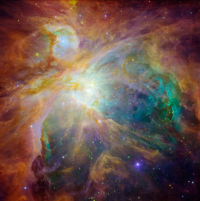
Orion  Nebula It is very important to make observations at different wavelengths as we get different information by looking at different wavelength bands. For example, stars and planets that are just forming lie hidden behind cocoons of dust and cannot be seen in visible light. The same is true for the very center of our Galaxy. However, infrared light can penetrate this dusty shroud and reveal what is inside. An example is the image of the Orion Nebula at left that combines Infrared and visible-light data from both the HST and the Spitzer Space Telescope.

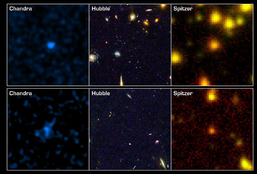
Orion Nebula Other objects may not emit visible or infrared light and may only emit X-rays. Or different regions of an object might emit light of a different wavelength than another region. We then need a telescope that can detect X-rays. Thus data obtained at different wavelengths can be combined to provide a more complete picture. For example, the image on the left shows the same two patches of sky, as viewed by an X-ray telescope (Chandra), a visible-light telescope (HST), and an infrared telescope (Spitzer). Each observation shows us something different (in this case, scientists were looking for black holes) - but combining these observations can give us a more complete (and more accurate) picture.
[top]


Size

size comparison HST is 13.2 meters (43.5 ft.) long and its maximum diameter is 4.2 meters (14 ft.) It is about the size of a large tractor-trailer truck. By contrast, JWST's sunshield is about 22 meters by 12 meters (72 ft x 39 ft). A Boeing 737-200 is 100 feet long!

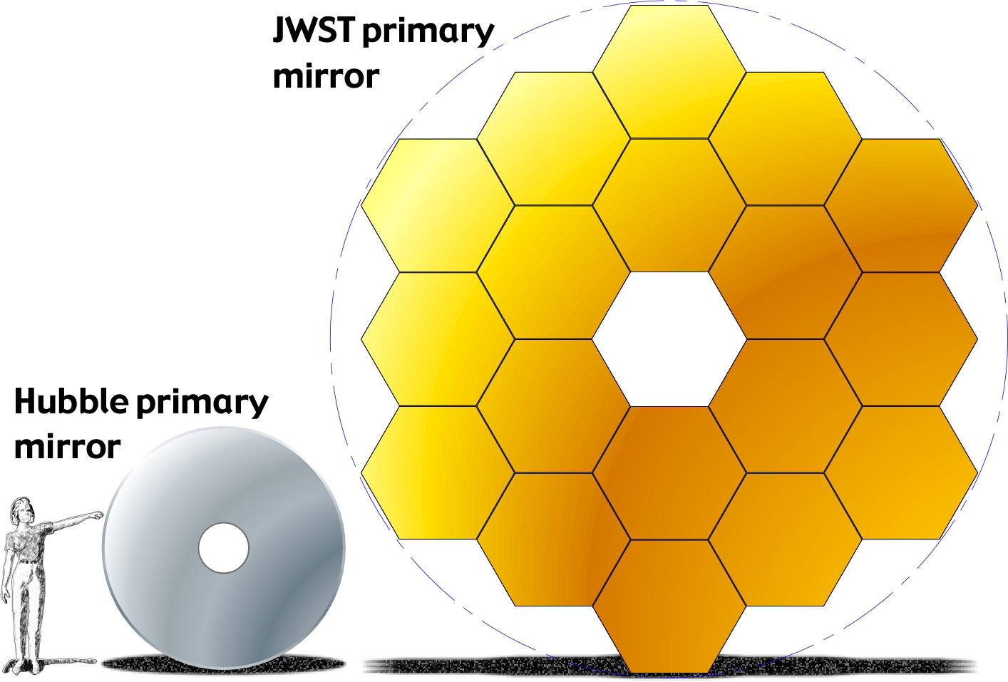
JWST and Hubble mirror  comparison JWST will have a 6.5 meter diameter primary mirror, which would give it a significant larger collecting area than the mirrors available on the current generation of space telescopes. HST's mirror is a much smaller 2.4 meters in diameter and its corresponding collecting area is 4.5 m2, giving JWST around 7 times more collecting area! JWST will have significantly larger field of view than the NICMOS camera on HST (covering more than ~15 times the area) and significantly better spatial resolution than is available with the infrared Spitzer Space Telescope.

[top]

Orbit

The Earth is 150 million km from the Sun and the moon orbits the earth at a distance of approximately 384,500 km.

earth sun distance  graphic

The Hubble Space Telescope orbits around the Earth at an altitude of ~570 km above it.

JWST will not actually orbit the Earth - instead it will sit at the L2 Lagrange point, 1.5 million km away! Because HST is in earth orbit, it was able to be launched into space by the space shuttle. JWST will be launched on an Ariane 5 rocket and because it won't be in earth orbit, it is not designed to be serviced by the space shuttle.

HST, JWST distance  graphic

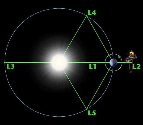
A Lagrange point is one of the five positions in interplanetary space where a small object (like a satellite) can be relatively stationary with respect to two larger objects (like the Earth and the Sun). It is analogous to an earth satellite in a geosynchronous orbit that allows it satellite to stay stationary over one spot on the Earth. At a Lagrange point, a satellite can stay "fixed" in space, rather than orbiting the Earth.

lagrange  diagram JWST will sit at the L2 point, with its solar shield blocking the light from the Sun, Earth, and Moon. This is very important as it will help JWST stay cool, which is very important for an infrared telescope. As the Earth orbits the Sun, JWST will orbit with it - but stay fixed in the same spot with relation to the Earth and the Sun, as shown in the diagram to the left.


Why does JWST need to be at L2?


JWST requires a distant orbit for several reasons. JWST will observe primarily the infrared light from faint and very distant objects. But all objects, including telescopes, also emit infrared light. To avoid swamping the very faint astronomical signals with radiation from the telescope, the telescope and its instruments must be very cold (Operating Temperature: under 50 K (-370 deg F)). Therefore, JWST has a large shield that blocks the light from the Sun, Earth, and Moon, which otherwise would heat up the telescope, and interfere with the observations.

To have this work, JWST must be in an orbit where all three of these objects are in about the same direction. The most convenient point is the second Lagrange point (L2) of the Sun-Earth system, a semi-stable point in the gravitational potential around the Sun and Earth. The L2 point lies outside Earth's orbit while it is going around the Sun, keeping all three in a line at all times. The combined gravitational forces of the Sun and the Earth can almost hold a spacecraft at this point, and it takes relatively little rocket thrust to keep the spacecraft near L2. The cold and stable temperature environment of the L2 point will allow JWST to make the very sensitive infrared observations needed.

Cosmic Quest at the Canada Science and Technology Museum


Date

20th May || 10 a.m. to 10 p.m. (Eastern time)


Location

Canada Science and Technology Museum

1867 St Laurent Blvd

Ottawa, Ontario, K1G 5A3


Senior Project Scientist for JWST (and Nobel Prize winner) John Mather is going to be giving a public talk in Ottawa at the Canada Science and Technology Museum on May 20th.


Cosmic Quest at the Canada Science and Technology Museum

Discover the Universe: Celebrate the International Year of Astronomy!

Discover the James Webb Space Telescope (JWST), successor to the famed Hubble Space Telescope, at the Canada Science and Technology Museum. In the daytime, meet Canadian Space Agency's team and try a series of interactive games and activities to learn more about the science behind JWST. Find out how Canada is part of this exciting new space observatory, which will be launched in 2013.

In the evening, join JWST scientists for two special presentations on JWST. Nobel Prize winner, John Mather, will kick off the evening with his presentation entitled "From the Big Bang to the Nobel Prize and the James Webb Telescope." Canadian scientist René Doyon, named Scientist of the Year by Radio-Canada, will follow with « À la recherche de nouveaux mondes » (The Search for New Worlds), in French. End the evening on a starry note by taking a planetarium show, or by heading outside for a star party (weather permitting). Astronomy experts will be available to answer all your stellar questions!

** All evening activities are free of charge. For daytime activities, regular Museum admission fees apply.

See the complete program.

Websites:

Canada Science and Technology Museum
James Webb Space Telescope

A Model Home For NASA's New Space Telescope


NASA commissioned construction of an environmental simulation test chamber which was completed in 1964 at Johnson Space Center (JSC) in Houston, Texas. The facility, Chamber A, was invaluable for testing spacecraft and satellites before deployment to space. By testing spacecraft in an environment similar to the one they would be functioning in, potential problems could be addressed before launch.

A new addition to NASA's observatory inventory is called the James Webb Space Telescope (JWST), after a former Administrator of NASA. The new telescope will have seven times the mirror area of the Hubble, with a target destination approximately one million miles from earth. Scheduled for launch in 2013, the JWST will allow scientists the ability to see, for the first time, the first galaxies that formed in the early Universe. Pre-launch testing of JWST must be performed in environments that approximate its final target space environment as closely as possible.

The Commission
JSC's Chamber A will require modifications to accommodate testing of the JWST. Some of these changes involve upgrades to cryogenic, vacuum pumping, and structural elements. To accomplish this, JSC presented a need for a 3-D model of the chamber and the surrounding area in its current state. This effort will provide engineers an accurate facility representation to be used in identifying and correcting any conflicts in upgrade design and installation.

To accomplish such a feat, NASA looked to Houston engineering firm, Taylor and Hill, Inc., who has been providing engineering services to the oil, gas, chemicals and power industries since 1974. The firm qualified as a category finalist in the Houston Business Roundtable award for "Outstanding Safety Performance" for 2003 and 2004 and received previous awards for outstanding safety leadership from BP South Houston in 1996, 1997, and 1999.

The project scope entailed scanning and modeling all eight levels, two large staging areas, two mechanical rooms and liquid nitrogen piping and storage tanks comprising the chamber and the area surrounding it.

"We were hired to identify the major obstructions, clearances and open areas surrounding the test chamber," noted Glen Kearns, Taylor & Hill's Laser Scanning Department Manager and Project Manager over this job.

The information would be used to facilitate the planning of new piping, electrical conduit runs, cable trays and equipment upgrades for the 118ft. tall chamber.

Obstacles
The project was marked high priority status by NASA, and therefore the measurements had to be completed in a timely manner. Construction and maintenance had already begun, which meant Taylor & Hill would be operating within a confined workspace.

Conventionally, engineers would gather the necessary data by using tape measures, photographs, and written notes to generate 2-D drawings. This would have been quite time consuming, obtrusive and open to error. "There would have always been the risk of overlooking something," Kearns stated.

Technology Suited for the Job
Taylor & Hill employed a method known as Laser Scanning Metrology (LSM) to gather all the necessary measurements. LSM involves using high-speed computer-aided laser scanners to generate high-accuracy measurements that are digitally recorded for 2-D and 3-D modeling, inspection, visualization or reverse engineering. The practice has been useful for a variety of applications, ranging from documenting as-is conditions for accident reconstruction or building renovations to reverse engineering boat hulls to virtual asset management of power facilities.

Using the Laser Scanner LS from FARO Technologies, and a combination of modeling and CAD softwares, Rito Morales and Don Meyer of Taylor & Hill produced the requested deliverables ahead of schedule.

FARO's Laser Scanner LS operates via phase shift technology by emitting a beam from the instrument's laser sensor to a vertical mirror. The beam is then deflected onto the object or environment being scanned. This includes full horizontal 360 degree coverage and vertical 320 degree coverage within a distance of 76m (249ft.). Finally, the beam is diverted back to the laser scanner and the distance coordinates are digitally recorded via angular encoders that measure the rotation of the vertical mirror and horizontal axis of the laser scanner. These X, Y Z coordinates are computed at a rate of nearly 120,000 points per second. A scan at minimal resolution can be completed in less than a minute.

"The speed at which the data was collected with FARO's phase-based scanner is a major consideration," Kearns observed. "Traditional methods would have taken several weeks or months to collect the data we gathered in about ten days of scanning."

The resulting points produce a high resolution picture-quality image with a major advantage­the data is represented in 3-D. The image, also known as a point cloud, contains all the scanned coordinates. This allows operators not only to have an accurate representation of the physical appearances of the scanned items, but also to obtain useful measurements for inspection, analysis and modeling.

Taylor & Hill produced more than 170 point clouds from the data collected throughout the 10 days on the job site. Off-site, all laser scans were registered using FARO Scene point cloud software to a building coordinate system established through dimensional control.

From the registered point clouds, 3-D solid models were developed through INOVx 3-D PlantLINx® showing objects outside of the chamber: floors, columns, major equipment and large diameter piping. They also furnished a detailed model of the steel that makes up the roof structure. The 3-D model was then exported into AutoCAD where final presentation visuals were added. Surface finishes were applied and rendered images were generated complete with lights and shadows.

"Contractors responsible for the upgrades are now aware of the obstacles that may impede their plans," stated Kearns.

Software Focus
FARO Scene is a high-performance and practical 3-D point cloud software tool designed for viewing, administrating and working on 3-D scan points from high-resolution 3-D laser scanners. This tool allows the user to manipulate raw 3-D scan points and acquire with analysis functions initial point-cloud data comprehension. Through data analysis and manipulation, scan points may be prepared for export into the user's operating platform as targets (.cor), scan points (.dxf, VRML, .igs, .pts, .ptx, .ptc), CAD objects (.igs, .dxf) or scan pictures (.jpg).

FARO Scene features:
• Measures distances between objects
• Completes point cloud filtering, compression, noise reduction and registration
• Analyzes CAD models against point clouds to recognize collisions and deviations
• Models basic graphical objects such as planes, spheres, and cylinders from point clouds

3-D PlantLINx converts the output of laser scanning and survey data into accurate 3-D models of existing plants. This is achieved through the creation of physical databases consisting of analysis of laser scans, stereo photos and survey points captured during field data collection utilizing automated surface modeling or assisted primitive modeling. Based on the level of detail required for a specific project, 3-D PlantLINx databases can be composed of conceptual, single revamp, major revamp or intelligent models.

3-D PlantLINx features:
• Processes laser images from most major laser scanning systems
• Rapid access to logical and complete regions of points
• Ability to customize or use industry standardized specifications for selected piping, structural steel and electrical elements
• User Defined customizable catalogs for complex assemblies, such as pumps, vessels, platforms, portable equipment, etc.
• Assisted 3-D modeling enables rapid creation of complete and accurate CAD geometry, including entire piping systems
• Structures 3-D models into userdefined conventions such as P&ID
• Roll based with optional concurrent user database access for increased modeling and QA/QC efficiency

Rito Morales is the CAD Support and Laser Scanning Specialist for Taylor & Hill, Inc. based in Houston, Texas. He has seven years of field experience with laser data collection in the petrochemical industry. A 1.956Mb PDF of this article as it appeared in the magazine—complete with images—is available by clicking HERE

JWST Instruments


The JWST instrument suite will consist of three science instruments. Unlike the Hubble Space Telescope, the JWST will be in a second Lagrange point orbit and will not be serviceable. Therefore, these will be the only instruments JWST will ever have.

JWST Science Instruments

MIRI Mid Infrared Instrument
NIRCam Near Infrared Camera
NIRSpec Near Infrared Spectrograph
FGS-TFI Fine Guidance Sensor Tunable Filter Imager


Supporting Hardware

ISIM Integrated Science Instrument Module
Guider Fine Guidance Sensor

JWST Science Goal


The James Webb Space Telescope (JWST) is a key element in NASA's Origins program, which has the goal of understanding the formation of galaxies, stars, planets and ultimately, life. JWST is specifically designed for discovering and understanding the formation of the first stars and galaxies, measuring the geometry of the Universe and the distribution of dark matter, investigating the evolution of galaxies and the production of elements by stars, and the process of star and planet formation. This is a document from JWST project website at NASA/Goddard describing the basic science objectives of JWST (pdf).

Public
JWSTSite gives a down-to-earth descriptions (without the astronomy jargon) of JWST science.
Scientists
A more scientific description can be found at the JWST Science Goals web pages of the Goddard JWST Project Center.
Experts
The NGST Ad Hoc Science Working Group developed the Design Reference Mission (DRM), a large number of observing programs to identify the core science program for the JWST. The DRM is used to guide telescope, instrument, and satellite designs.

The NGST Ad Hoc Science Working Group created in 1999 the Design Reference Mission (DRM), a set of hypothetical observing programs identifying a core science program for the JWST. Associated with these observing programs, a suite of potential astronomical targets were identified, each with their expected physical properties (number density and brightness) and desired observation modes (wavelength band, spectral resolution, number of revisits). Using the JWST Mission Simulator (JMS) each possible JWST design is tested for accomplishing the most number of DRM goals within the allotted time and budget.

JWST Project History


The links below provide the history of the conception and development of JWST thus far. These pages are partly based on a presentation given by Peter Stockman (JWST/STScI Project Scientist) at the 2001 Hubble Fellows Symposium.

Prior to September 10, 2002, the JWST was known as the Next Generation Space Telescope (NGST). In the pages below we will reference the name of the observatory that was in use at the time of a given milestone.

  • 1989-1994 Conception, the early years
  • 1995-1996 Stepping up the bid, going for 8 meters
  • 1997-2001 Reality hits, re-scope to 6m
  • 2002 Selecting the partners
  • 2003-2004 Working on the Detailed Design
  • 2005 The First Major Reviews and a Financial Shock
  • 2006 Back on Track
  • 2007 Approaching Preliminary Design Review